
Commercial and Industrial Battery Energy Storage Supply for EPCs and Integrators
- 256 V 76.8 kWh high-voltage modules
- 500 kW – 1 MW containerised systems
- CAN / RS485 to mainstream PCS
- 6,000 cycles with stated test conditions
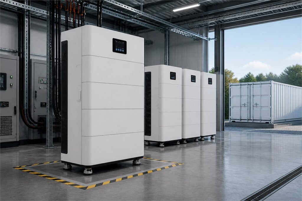
Catalog range
256 V · 300 Ah · 76.8 kWh per module · 1–4 parallel · 500 kW–1 MW containers
Who specifies C&I storage
EPC contractors
- PCS and protocol confirmation
- Module and container formats
- Project documentation package
System integrators
- CAN / RS485 interfaces
- Documented protocol behaviour
- Repeatable configuration across sites
Energy developers and asset owners
- Warranty term and throughput basis
- Certification and test evidence
- Long-term supply and spares
Two numbers size a C&I system, and most enquiries send only one
| Step | What to determine | Typical source |
|---|---|---|
| 1 | Target energy capacity, kWh | Duration of the peak to be covered |
| 2 | Peak power requirement, kW | Demand charge to be shaved |
| 3 | Cycles per day | Tariff structure and strategy |
| 4 | Module or cluster count | kWh target divided by unit capacity |
| 5 | PCS rating and protocol | Existing selection or joint sizing |
| 6 | Thermal and fire strategy | Site conditions and local code |
Platforms specified for commercial and industrial projects
256 V high-voltage modules
- 76.8 kWh per module
- 100 A charge and discharge
- 1 – 4 in parallel, 6,000 cycles
500 kW – 1 MW containers
- Turnkey container format
- Integrated thermal management
- Project-specific configuration
LD 48684 — 35 kWh cabinet
- 35.02 kWh per unit
- 15 units in parallel
- CAN / RS485 / RS232
What has to be settled before a project quotation means anything
Load profile, not just peak demand
PCS make, model and protocol
Cycles per day drives the economics
Thermal strategy and site conditions
Fire safety and local code
Warranty basis — years or throughput
Indicative system sizing by application
| Application | Typical energy | Typical power | Starting configuration |
|---|---|---|---|
| Workshop or small factory evening peak | 35 – 70 kWh | 30 – 50 kW | 1 – 2 LD cabinets |
| Retail or hospitality demand shaving | 75 – 150 kWh | 50 – 100 kW | 1 – 2 high-voltage modules |
| Mid-size factory peak shaving | 150 – 310 kWh | 100 – 200 kW | 2 – 4 high-voltage modules |
| Solar self-consumption, commercial roof | 200 – 500 kWh | 100 – 250 kW | Multiple clusters or container |
| Site backup with critical loads | 300 – 800 kWh | 200 – 500 kW | Containerised system |
| Grid support and arbitrage | 1 MWh and above | 500 kW – 1 MW | Container, multiple units |
Evidence a commercial project and its financier will ask for
- IEC 62619 / IEC 63056 safety test evidence
- UN38.3 Test Summary and SDS for shipment
- Dangerous goods packaging documentation for sea freight
- CE Declaration of Conformity for EU placement
- UL 1973 and UL 9540 listing where North American code requires it
- UL 9540A fire propagation test data where the AHJ requests it
What can be configured for a project or an integrator programme
- Module count, cluster architecture and parallel topology
- BMS thresholds and protection coordination
- Communication protocol matched to the selected PCS
- Enclosure format, ingress rating and thermal approach
- EMS integration and monitoring interfaces
- Documentation package for AHJ, insurer and financier review
Technical and commercial questions
Determine the target energy capacity in kWh from the duration of the peak you need to cover, then the peak power requirement in kW from the demand charge you are shaving. Divide the kWh target by the unit capacity to get module count, then check that the resulting power rating meets the kW requirement. Both checks have to pass.
The battery communicates over CAN and RS485 to mainstream power conversion systems. Compatibility is confirmed at model and firmware level rather than brand level — send the exact PCS selection and we will confirm the protocol settings before the order rather than during commissioning.
It is specified at 25 °C and 80 % depth of discharge. At one cycle per day that is roughly sixteen years, which exceeds the calendar life of the hardware. At two cycles per day it is around eleven years and becomes the binding constraint. Which case applies changes what specification is worth paying for.
Active fire suppression is available as an option on selected platforms, and thermal management is integral to the container systems. Requirements vary sharply by jurisdiction, so raise the local code position at design stage — it drives siting, separation and detection, not just the enclosure.
A term in years alone leaves too much room for dispute. Ask for the capacity retention threshold and, where possible, an energy throughput limit. A warranty stated as a term or a throughput, whichever comes first, is a supplier putting a number behind the cycle life claim.
Send the information request. We will provide the test evidence, certification scope and manufacturing documentation we hold, and state plainly what we do not hold rather than leaving a gap for someone to discover later.